
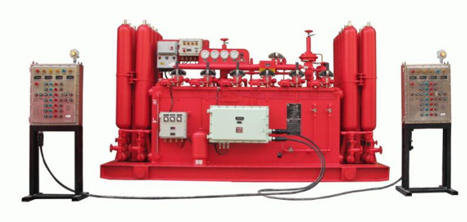
The FKDQ-type blowout preventer control unit operates on an electro-pneumatic-hydraulic control principle and consists of a main console, auxiliary console, communication cables, etc. The main console is composed of an oil tank, pump unit, accumulator bank, control manifold, solenoid valves, and an electric control box. The auxiliary console consists of a button box, PLC, etc. High-pressure hydraulic fluid generated by the electric pump unit is stored in the accumulators. When it is necessary to open or close the blowout preventer or hydraulic valves, simply operate the buttons on the auxiliary console to remotely control the switching actions of the rotary valves; the high-pressure hydraulic fluid from the accumulators is distributed to each controlled object through three-position four-way rotary valves.
|
Model |
Number of Controlled Objects |
Effective Volume of Oil Tank (L) |
Total Volume of Accumulator (L) |
Available Liquid Volume of Accumulator Bank (L) |
Displacement of Electric Pump (L/min)) |
Displacement of Pneumatic Pump (ml/stroke) |
Motor Power (KW) |
L× W × H (mm) |
|
FKDQ320-4 |
4 |
650 |
320 |
160 |
24 |
175 |
11 |
3960X2230X2340 |
|
FKDQ400-5 |
5 |
890 |
480 |
240 |
32 |
350 |
15 |
4460X2440X2610 |
|
FKDQ640-6 |
6 |
1300 |
640 |
320 |
42 |
350 |
18.5 |
3900X2150X2250 |
|
FKDQ720-6 |
6 |
1500 |
720 |
360 |
42 |
350 |
18.5 |
5460X2230X2360 |
|
FKDQ800-8 |
8 |
1500 |
800 |
400 |
42 |
350 |
18.5 |
6200X2478X2610 |
|
FKDQ1280-10 |
10 |
2600 |
1280 |
640 |
84 |
525 |
37 |
5400X2230X2340 |

 返回列表
返回列表